Hardware blocks pinout
View pdf document on hardware blocks connections
Hardware blocks pinout documentation
View pdf document on hardware blocks connections
Hardware blocks pinout documentation
Stack Electronics Overview
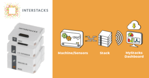
Interstacks is a system of modular electronic blocks and the integrated MyStacks IoT cloud platform for rapidly deploying industrial IoT and remote monitoring solutions. Interstacks makes it easy to get machines, sensors, and things directly connected to dashboards with storage, visualization, analytics and text/email alerts. From any web browser on any desktop or mobile device, the real time data can be viewed. Sensors or machine data feeds are connected to a stack then the data is sent over ethernet, wifi, or cell network to the MyStacks IoT cloud platform and/or other servers using web standard REST APIs, Modus RTU, or Modbus TCP.
This document will give an overview of the stack electronics. “Stacks” are the modular electronics that capture data from sensors and machines. They are 2” x 2” snap-together blocks, with mating connectors on the top and bottom. Each block performs a unique function. Every stack requires one Base at its bottom. As few or as many blocks as you need, in whatever order you desire, are snapped together above the Base. All of the blocks in a stack communicate with each other over multiple serial data busses via the top/bottom mating connectors. A stack is powered via a coaxial connector on the Base (5V DC). The Base has a 1 GHz processor with 512MB Ram and 16GB flash that runs a Python programming language virtual machine. It does not use the Linux or any other conventional operating system. Python application software is developed and downloaded into a Base from a laptop using the Interstacks Stackbuilder development tool. Projects are typically assigned a support engineer who can pre-program your stack for your specific needs, set up initial cloud dashboards, and make sure the project is a success. Other electronic blocks use microcontrollers of various sizes. Firmware in those blocks implement the block’s functions and send and receive messages over the serial data busses in the stack. A typical stack has a Base at its bottom, plus some number of I/O blocks, then a network communication block on top (Ethernet, Wifi, Cell data). Multiple network communication blocks can be used.
Each electronic block has a LED light in its corner. That light can be green, red, or orange. Red indicates a fault condition. Green indicates normal operation. The light will flash orange as it sends or receives messages from other blocks. Network blocks will flash orange rapidly in an even pattern as they are looking for a network connection (this only indicates an IP address has been assigned, not that there is a connection to the internet or servers – network firewalls could still prevent that). The rapid orange flashing will stop once a network connection is established. The network block will still flash orange intermittently as it sends and receives messages.

There are many blocks available and new ones are being added on a regular basis. Blocks include: the Base, Analog input (8 channels individually configurable), I/O Expander (8 channels for switch inputs or 3.3v logic outputs), serial data UART, RS-232, RS-485, Barcode, USB keyboard, Bluetooth, Ethernet, Wifi, and Cell data network communications, plus many more. The cell data block incorporates a SIM that can be activated for any country (data plan required). See the Interstacks website for more information and to order.
There are many support documents online in the support area of our web site at https://www.interstacks.com/knowledge-base/
Email: info@interstacks.com
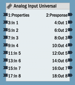
The Analog In Universal hardware block allows you to connect a wide range of sensors and other devices to an Interstack’s stack.
It has eight universal analog inputs, each individually configurable for behavior and analog input voltage range plus a mode for 4 – 20mA current loop input. It outputs a 16 bit integer ( 0 to 65,535) representing the input voltage on one of its input channels. There are 10 different input ranges that can be selected, from +/- 0.64V DC all the way to +/- 10V DC (see details below). Sensors and devices often use widely different electrical interfaces. The most popular interfaces for sensors are 0 – 5V DC, 0 – 10V DC, and 4 – 20mA current loop.
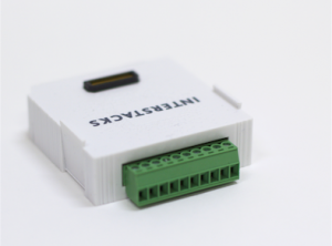
There is a ten screw terminal connector on back for connecting wires to the block from the external devices. The connector block can also output 3.3V or 5V for powering an external device.
There are many vendors to purchase sensors that can be connected to Interstacks. Contact us at info@interstacks.com for help.
You can individually change the function of each of the eight inputs of the Analog In Universal hardware block by editing their corresponding property in the “Property Editor” in the bottom right of Stackbuilder.
To set properties in Stackbuilder: Select the Analog In Universal block by clicking on it once. Click in the “Property Editor” in the bottom right, in the “Initial Value” column for the property you want to edit (if a character or string, use quotes). You typically need to set the input channel’s behavior via the HT1_Mode (through HT8_Mode) properties and the input voltage range via the HT1_input_voltage_range (through HT8_input_voltage_range) properties.
Property HT1_Mode specifies the function of input channel 1 (the leftmost connection, looking into the back of the block).
Analog In Universal Connector – Looking into back

DC Out is 3.3V if property V is 1 (default). 5V if property V is 0. Can supply 400 mA.
Analog input signals
For analog input signals, there are a number of signal processing features that can be enabled by setting the property for the I/O pin. The property set to 1 will simply read the input and output a number 0 -65,535 whenever requested by sending any message to the input terminal that corresponds to that pin. If set to 2, the value will be automatically sent if its value changes by greater than the corresponding hysteresis property e.g. ‘HT1_Hysteresis’’. If set to 3, a ‘1’ will be output if the value is greater than the comparison property e.g. ‘HT1_Threshold’. If set to 4, the value will be output every xxxx milliseconds based on the rate property for the pin e.g. ‘HT1_Rate’.
Properties
HT1_Mode through HT8_Mode (int): Define behavior of I/O1 – I/O 8
0 Inactive
1 Analog input on demand. Output terminal will output an int (0 – 65,535) based on analog voltage of I/O pin when requested by sending any message to the corresponding input terminal.
2 Analog input send change. Will output analog value on any change while filtering based on the value of the HTx_Hysteresis (hysteresis) property for that pin.
3 Analog input with compare. Outputs a ‘1’ on change to above HTx_Threshold property. Outputs a ‘0’ on change to below comparison value property HTx_Threshold for that pin.
4 Analog input, send every x milliseconds based on update rate property HTx_Rate for that pin.
HT1_Hysteresis through HT8_Hysteresis (int): Hysterisis value for analog input send on change. default is 50.
Each input used as analog input has its own hysterisis property, hence HT1_Hysteresis through HT8_Hyesteresis.
If analog input signal is noisy, use a higher value to reduce automatic value update sends.
HT1_Threshold through HT8_Threshold (int): Comparison value for analog input compare mode. default is 32,000.
HT1_Rate through HT8_Rate (int): Update rate, in milliseconds (1000 is 1 second), for analog input update rate mode.
HT1_input_voltage_range through HT8_input_voltage_range: Sets the analog input voltage range or 4 – 20mA input for that channel.
0 Nothing. default
1 0-20mA current loop
2 0-5V
3 0-10V
4 0-2.5V
5 0-1.28V
6 +/- 10V
7 +/- 5V
8 +/- 2.5V
9 +/- 1.28V
10 +/- 0.64V
Voltage (int): 0 to set external power terminal to 5V. 1 for 3.3V (default).
Type (T) (uuid): Module Type
Version (F) (int): Firmware Version
Terminals
“Properties” – in (List or Property Name string): To set property. Send property name, Value. For example [’N’,’netname’].
To get property, just send property name. For example. ’N’
“Presponse” – out (List or True) : On set, responds with True when done.
On get, responds with list. For example [’N’, ‘netname’].
Terminals Out 1 – 8. See above description of properties HT1_Mode – HT8_Mode.
“Out 1”
“In 1″
…
“Out 8”
“In 8″
If property defines pin as an active analog input, will output integer for pin’s analog value. Outputs an integer number 0 – 65,535.
If analog input with compare, outputs on change character ‘0’ if below compare value and ‘1’ if above.
In HTx_Mode equal to 1, any message to the corresponding input terminal will cause the analog value to be sampled and sent out the output terminal.
Refer to documentation on many other topics at interstacks.com/knowledge-base.
Please email info@interstacks.com with any questions.
Use the Ethernet hardware block to connect your stack to your local LAN network and the internet if it is connected to your router. In your Stackbuilder blueprint, drag and drop the Ethernet block from the Hardware tab into your blueprint. The connector is a standard RJ-45 connector.
To set properties in Stackbuilder: Select the Ethernet block by clicking on it once. Click in the “Property Editor” in the bottom right, in the “Initial Value” column for the property you want to edit (if a character or string, use quotes).
Use other blocks, like “Interstack Send” or “Interstack Receive” (in Hardware tab) or “HTTP API” block (in Software tab) to communicate with other stacks, and web sites or industrial IoT platforms on the internet or on-premise.
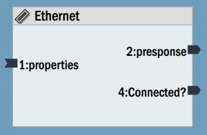
Status (int): Connection status. Read Only. 0 if not connected. 1 if connected to network. 2 if dhcp assigned successfully. This int is also sent out terminal 1 on change.
Mode (int): Module mode: 0 Client mode (default), 2 Simultaneous AP and Client, 3 AP access point mode only.
ID (Any) : Any value, typically a string, that describes location of stack. This is sent, or received, to indicate a stack’s location during stack to stack messaging. (The ‘L’ property in an individual stack-to-stack send or receive block can override this value for that block only).
AP_network_name (string): Network name, SSID, of access point to which clients connect.
AP_password (string): Password for access point of stack for client connections.
AP_subnet_mask (string): Subnet mask for stack access point.
AP_ip_address (string): Set IP address for AP (access point). String up to 15 characters. xxx.xxx.xxx.xxx. Default is 192.168.88.1
AP_router (string): IP address of the router/gateway to provide to DHCP clients. Default is 0.0.0.0 providing no routing to clients.
Cloud_address (string): IP address of Interstacks cloud services (currently discovery.interstacks.com for cloud discovery of stack to stack and message relay.
Block properties and terminals
Properties
Refer to documentation on many other topics at interstacks.com/knowledge-base.
Please email info@interstacks.com with any questions.
Connect your stack to a RS-485, multi-drop serial network. Set your baud rate (speed) and whether you want a network termination resistor via properties in the blueprint you create using the Stackbuilder authoring tool. There are many message protocols that run on RS-485 networks, for example MODBUS, MODBUS RTU, DMX512, and proprietary machine specific formats. Use built-in software blocks, or software blocks you create using Python scripting in Stackbuilder, to parse and send messages.
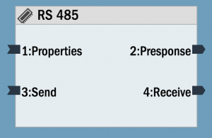
To set properties in Stackbuilder: Select the RS-485 block by clicking on it once. Click in the “Property Editor” in the bottom right, in the “Initial Value” column for the property you want to edit (if a character or string, use quotes).
RS-485 connector – Looking into back
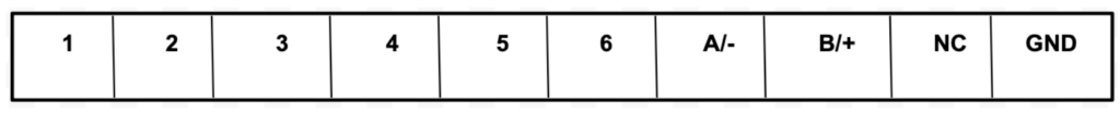
The A (D-) and B (D+) screw terminals are used to connect to the network.
Block properties and terminals
Properties
Type (T) (uuid): Module Type
Version (F) (int): Firmware Version
u_baud (B) (int): Uart baud rate. default 9600 baud.
u_resistor (R) (int): If 1, connect the 120 ohm network terminating resistor. 0 to not connect (default).
Terminals
“Properties” – in (List or Property Name string): To set property. Send property name, Value. For example [’N’,’netname’].
To get property, just send property name. For example. ’N’
“PResponse” – out (List or True) : On set, responds with True when done.
On get, responds with list. For example [’N’, ‘netname’].
“Send” – in (String, Binary, int): send string to UART, we only send valid ascii portion. Also accept binary raw bytes. Also int < 256. send out as raw byte.
“Receive” – out (String): Single byte received by UART. sent as String.
For the DMX512 message protocol, send [1,100] to the send terminal to generate a 100uS break. Send [2,20] to generate a 20uS mark after break.
Refer to documentation on many other topics at interstacks.com/knowledge-base.
Please email info@interstacks.com with any questions.
The I/O pH ORP block supports connecting pH and ORP electrode sensors (not included) for measuring water quality. It also has a general I/O pin that can be used for a digital or analog (3.3V) connection and two switched relay outputs that have a common terminal.

ph and ORP sensors are often used to measure water quality. They are passive electrodes that require special signal conditioning electronics. They are connected to the pH-, pH+, ORP-, and ORP+ screw terminals on the back of the module. The sensors will output analog values between 0 and 670 over their full range. You can calibrate the sensors using standard test solutions. A lower pH will be a higher number, a higher pH a lower number. Neutral pH will output approximately 330 on the “Out 1 pH” terminal. ORP oxidation range will be a higher number and ORP reduction range will be a lower number (than neutral 330). Note that the typical lifetime of sensor probes is 12 – 18 months and they need to be stored in solution. Please read your sensor probe documentation for more information.


Relay Outputs
When using the relay outputs, connect the ground for the power supply powering your loads (solenoids, valves, etc) to the Relay Common terminal. Connect one end of your loads to the positive voltage of your power supply and the other end of your loads to the Relay 1 or Relay 2 terminal. The relay outputs are rated at 0 – 60 V DC max and 700 mA current max. If you need to switch higher voltages or AC power, you can connect inexpensive external relay adapters to the Interstacks I/O Expander block.

To set properties in Stackbuilder: Select the I/O ph ORP block by clicking on it once. Click in the “Property Editor” in the bottom right, in the “Initial Value” column for the property you want to edit (if a character or string, use quotes).
Block properties and terminals
Properties
T (uuid): Module Type
F (int): Firmware Version
HT1_Mode through HT3_Mode (int): Define behavior of I/O1 – I/O 3
0 nothing – never does anything.
1 Digital Output. Input terminal character ‘0’ or ‘1’ will make I/O pin low or high.
2 Digital Input. Output terminal will output character ‘0’ or ‘1’ dependent on state of I/O pin when requested by sending any message to the corresponding input terminal.
3 Digital Input Send Change. Will output on any state change.
4 Analog input on demand.
Output terminal will output an int (0 – 1000) based on analog voltage of I/O pin when requested by sending any message to the corresponding input terminal.
5 Analog input send change. Will output analog value on any change while filtering based on the value of the HTx_Hysteresis (hysteresis) property for that pin.
6 Analog input with compare. Outputs a ‘1’ on change to above HTx_Threshold property. Outputs a ‘0’ on change to below comparison value property HTx_Threshold for that pin.
7 Analog input, send every x milliseconds based on update rate property HTx_Rate for that pin.
8 Digital input, accumulate duty cycle – Send update every HTx_Rate mS.
Accumulates the amount of high signal during update and sends this as value (currently samples once per mS).
(Have used with dust sensors (particulates)).
9 Digital edge count – send number of edges counted every HTx_Rate mS. (min 1ms pulses)
HT1_Hysteresis through HT3_Hysteresis (int): Hysterisis value for analog input send on change. default is 5. (multiples of about 3mV).
Each input used as analog input has its own hysterisis property, hence HT1_Hysteresis through HT8_Hyesteresis.
If analog input signal is noisy, use a higher value to reduce automatic value update sends.
HT1_Threshold through HT3_Threshold (int): Comparison value for analog input compare mode. default is 500.
HT1_Rate through HT3_Rate (int): Update rate, in milliseconds (1000 is 1 second), for analog input update rate mode.
Voltage (int): 0 to set external power terminal to 5V. 1 for 3.3V (default).
Terminals
“Properties” – in (List or Property Name string): To set property. Send property name, Value. For example [’N’,’netname’].
To get property, just send property name. For example. ’N’
“Presponse” – out (List or True) : On set, responds with True when done.
On get, responds with list. For example [’N’, ‘netname’].
“Read pH” – Any message will send value out of output terminal if HT1_Mode set to 4.
“Read ORP” – Any message will send value out of output terminal if HT2_Mode set to 4.
Terminals In and out 3, . See above description of various properties 1-3 (HTx_Mode, HTx_Hysteresis, HTx_Threshold, HTx_Rate).
“Out 1 pH” Uses HT1 properties for analog inputs.
“Out 2 ORP” Uses HT2 properties for analog inputs.
“In 3” Uses HT3 properties.
“Out 3” Uses HT3 properties.
If property defines I/O pin as output, character ‘0’ makes pin low, ‘1’ high.
If property defines I/O pin as digital input, will output character ‘0’ or ‘1’ based on level on I/O pin.
If property defines I/O pin as analog input, will output int with I/O pin analog voltage. Outputs a number 0 – 1000.
If analog input with compare, outputs on change character ‘0’ if below compare value and ‘1’ if above.
“Relay 1” – Input terminal character ‘0’ or ‘1’ will make relay 1 open or closed.
“Relay 2” – Input terminal character ‘0’ or ‘1’ will make relay 2 open or closed.
Note: Digital inputs configured with weak pullups. so can connect buttons without external resistor.
References
Texas Instruments – Designing with pH Electrodes App Note
http://www.ti.com/general/docs/litabsmultiplefilelist.tsp?literatureNumber=snoa529a
Support
Refer to documentation on many other topics at interstacks.com/knowledge-base.
Please email info@interstacks.com with any questions.
Use the Interstacks Cell Data hardware block to send text messages and connect to the internet over the cell data network. The Interstacks Cell Data hardware block is a 4G LTE CAT-1 cellular data module. It operates in the U.S. and Canada. Please contact us for other countries. We can provide a data plan with an embedded SIM in the module.


Sending Data to the Internet over the cell network
Unlike sending data to the internet over a Wifi network, every byte of data sent over the cell network incurs a cost to your data plan. Hence, please think about your system’s strategy for the amount and frequency of data sent, and hence the design of your stack’s blueprint. Typically you will send smaller amounts of data, less frequently than if using a wired ethernet or Wifi network.
Your Interstacks support engineer can pre-program your stacks for your specific requirements or you can use Stackbuilder to do your own programming.
Creating a Stack Blueprint that uses the Cell Data block
You will need to launch Stackbuilder and import the following blocks into your MyBlocks library.
Select “My Blocks” in the right rail, then under the “Blocks” pull down menu, select import.
Copy and paste the following ID into the import dialog: ~01076c962888ed11e79acce9b785b9bb4f
That imports “Cell Modem Block”.
Do the same for ID: ~0171793e1a665e11e7be28834f65bce283
That imports the “Cell UART HTTP API” block.
Finally, there is a full example project that can be imported using the following ID:
Select the “Projects” tab on the right rail, then “Import” from the “Blocks” pull down menu.
~0146792e4088f611e79accd85bf5a26e6b
This project will be Read Only, but you can view all of it and make a copy that you can edit.
Cell Modem Block – ~01076c962888ed11e79acce9b785b9bb4f
Description: This blueprint provides the hardware interface and related message parsing to communicate at the TCP level with flow control via a multiplexer that provides a maximum of 4 simultaneous TCP connections.
INPUT TERMINALS:
1:properties – Standard property get and set input terminal
3:init – Any message sent to this terminal will trigger the modem to activate and initialize. Typically the Base module’s “22:Stack Ready” output terminal is wired into this terminal.
5:send_sms – Attempt to send a message M to a phone number P specified in the following format as a string “P:M”
7:reset – Resets the modem.
9:tcpin_1 – This terminal is part of a multiplexer. This terminal receives TCP messages from a higher level block such as a Cell UART HTTP API Block
11: flowin_1 – This terminal is part of a multiplexer. This terminal is used in conjunction with the above terminal to provide flow control
The rest of the input terminals repeat the same functionality of the above two pairs thereby providing a maximum of 4 flow controlled TCP connections to the Cell Modem Block.
OUTPUT TERMINALS:
2:presponse – Standard property response output terminal
4:modem_status – This is similar to the WIFI module’s wifi_status terminal. Emitted message are 0, 1 or 2. The value of 2 indicates the cell modem is ready for communication. Typically this value is used to trigger the rest of the business logic that deals with REST calls with the cloud etc.
6:sms_sent – Provides the status of the last sms message that was sent via the modem. 0 indicates success, -1 indicates failure.
8:sms_received – When the cell modem receives a text/sms message, this terminal sends the message M received from phone number P in the following string format “P:M”
10:tcpout_1: This terminal is part of a multiplexer. This terminal sends TCP messages to a higher level block such as a Cell UART HTTP API Block.
12:flowout_1: This terminal is part of a multiplexer. This terminal is used in conjunction with the above terminal to provide flow control.
The rest of the input terminals repeat the same functionality of the above two pairs thereby providing a maximum of 4 flow controlled TCP connections to the Cell Modem Block.
Cell UART HTTP API Interface – ~0171793e1a665e11e7be28834f65bce283

Description: This block is functionally similar to the HTTP API Interface. For details on the HTTP API Interface, refer to interstacks.com/knowledge-base/internet-communication-with-http-block/
This extended blueprint exposes a pair of input and output terminals that can be connected into a Cell Modem Block’s multiplexer providing the TCP connection and flow controls.
PROPERTIES:
Same as the HTTP API Interface block. No new properties.
INPUT TERMINALS:
6:tcp_in – This receives TCP messages from any one of the multiplexed outputs of the Cell Modem Block.
8:flow_in – This is a corresponding flow control terminal of the above terminal.
OUTPUT TERMINALS:
8:tcp_out – This send TCP messages to any one of the multiplexes inputs of the Cell Modem Block.
10:flow_out – This is a corresponding flow control terminal of the above terminal.
The following is a sample project blueprint to illustrate the use of these blocks.
Cell Modem HTTP Example Project – ~0146792e4088f611e79accd85bf5a26e6b

Import the above UUID into Stackbuilder to try.
The example project illustrates sending data to a cloud (IBM Watson in this example) using the Cell Modem module. The Cell Modem Block is initialized by connecting the Base module’s “22:Stack Ready” output to the “3:init” terminal. This initiates the cell modem to start communicating with the network provider which may take a few seconds after which a message from “4:modem_status” with a value of 2 indicates the block is ready. In this example, the modem status is wired into the “test rest api” block that kickstarts a REST API call to the IBM Watson cloud using the Cell UART HTTP API block. Note the tcp and flow controls are wired to one of the corresponding terminals of the Cell Modem Block’s multiplexer.
Notes:
1) If the “4:modem_status” terminal does not emit the message 2 for more than 20 seconds after the stack is booted/running, try rebooting the stack and try again. Sometimes, the cell modem may not be able to acquire sufficient signal strength to communicate with the cell network infrastructure. It might also help moving the stack closer to a window or another place for better cell reception.
Refer to documentation on many other topics at interstacks.com/knowledge-base.
Please email info@interstacks.com with any questions.
Every stack must have a Superbase at its bottom. It runs the Python scripts in software blocks and is where power and the mini-USB cable used with Stackbuilder are connected. The most often used terminal is the “Stack Ready” output terminal. It is often used to “kick start” the data flow for a Stack’s Blueprint. You may also store a small amount of “Stack environment properties” in non-volatile memory in the Superbase. This might be some configuration preference information the user enters for a specific instance of a Blueprint in a specific stack. The Superbase also includes a real-time clock.


You connect your stack to your laptop for developing Blueprints via the mini USB connector on the left. DC Power (5V) is plugged into the stack using the coaxial barrel connector on the right.
Block properties and terminals
Properties
Type (uuid): Module Type
Version (int): Firmware Version
Construct_Usb (Boolean (True or False)): Construct on reset. (For developers only).
Partial (Boolean): Allow partial construction of a blueprint.
Reset_Bus (int): Hardware reset the stack if bus errors. 2 Hard reset, 1 Soft reset, 0 No reset. Default is 2.
Watchdog (Boolean): Enable hardware watchdog reset. Default is True.
Terminals
“Properties” – in (List or Property Name string): To set property. Send property name, Value. For example [’N’,’netname’]. To get property, just send property name. For example. ’N’
“PResponse” – out (List or True) : On set, responds with True when done. On get, responds with list. For example [’N’, ‘netname’].
“Request Random” – in (String): Trigger a random number 0-255 be sent out “Random Num” terminal.
“Random Num” – out (int): Sends random number 0-255 when triggered.
“Set/Get Time” – in (String): Any 1 char string triggers send time. If 6 char string, then sets. Time HHMMSS.
“Time HHMMSS” – out (String): Time HHMMSS.
“Set/Get Date” – in (String): Any 1 char string triggers send date. If 6 char string, then sets. Date MMDDYY.
“Date MMDDYY” – out (String): Date MMDDYY.
“Request Hour” – in (String): Request send of hour.
“Hour” – out (int): Outputs hour when any input string message and on change.
“Request Minute” – in (String): Request send of minute.
“Minute” – out (int): Outputs minute when any input string message and on change.
“Request Second” – in (String): Request send of second.
“Second” – out (int): Outputs second when any input string message and on change.
“Stack Ready” – out (Any): Outputs message when stack construction is completed. Used when needed, to “kick off” a Blueprint’s dataflow.
“Reset Stack” – in (String) Resets stack hardware if receives string “Reset”.
“Set Session” – in. (Dictionary) Python dictionary (attribute-value list) stored in non-volatile memory in Base.
“Set Session Status” – out (Boolean). True or False indicating success or failure for write of Session.
“Get Session” – in. (int) When sent a 1, sends Session out of Session terminal.
“Session” – out (Dictionary) Sends Python dictionary that was stored in Session or None.
Refer to documentation on many other topics at interstacks.com/knowledge-base.
Please email info@interstacks.com with any questions.
Use the Wifi hardware block to connect your stack to your local LAN network and the internet if it is connected to your router. In your Stackbuilder blueprint, drag and drop the Wifi block from the Hardware tab into your blueprint. Then click once on the Wifi block to select it. Use the Property Editor in the bottom right to set the ’Network_Name’ property for LAN network name (SSID), and the ‘Password’ property for the password. There are many other support documents that describe sending data to cloud platforms and using this Wifi module as both a client and an Access Point.
Set Properties for Wifi block
To set properties in Stackbuilder: Select the Wifi block by clicking on it once. Click in the “Property Editor” in the bottom right, in the “Initial Value” column for the property you want to edit (if a character or string, use quotes).


Set properties to connect to a LAN. Stack to stack communicaiton is done with Interstack Send and Interstack Receive blocks. Internet web communication is done with HTTP API block or TCP Client block.
Block properties and terminals
Properties
Type (uuid): Module Type.
Version (int): Firmware Version
Network_Name (string): Network Name. string up to 32 characters
Security (int): Security. 0 none 4 WPA2 (default).
Password (string): Password. 8 to 63 characters for WPA2. Write only.
DHCP (int): Use DHCP. 0 static IP. 1 use DHCP (default).
IP_Address (string): IP address. string up to 15 characters. from DHCP or manual static. xxx.xxx.xxx.xxx
Subnet_Mask (string): Subnet mask. string up to 15 characters. from DHCP or manual static
Router_Address (string): Router (Gateway) IP Address. string up to 15 character. from DHCP or manually static
DNS_Address (string): DNS Name server IP address. string up to 15 character. (from DHCP) or manually set.
DNS2_Address (string): DNS Name server2 IP address. string up to 15 character. secondary (from DHCP) or manually set.
MAC_Address (string): Wifi MAC address. Read Only. 17 character string. In case you need to provide to your IT department for secure network access.
RSSI (int): RSSI signal strength for connected network. Read only. signed 16 bit integer. negative number. closer to 0 is stronger signal.
Status (int): Connection status. Read Only. 0 if not connected. 1 if connected to network. 2 if dhcp assigned successfully. This int is also sent out terminal 1 on change.
Mode (int): Module mode: 0 Client mode (default), 1 No Wifi, 2 Simultaneous AP and Client, 3 AP access point mode only.
ID (Any) : Any value, typically a string, that describes location of stack. This is sent, or received, to indicate a stack’s location during stack to stack messaging. (The ‘L’ property in an individual stack-to-stack send or receive block can override this value for that block only).
AP_network_name (string): Network name, SSID, of access point to which clients connect.
AP_password (string): Password for access point of stack for client connections.
AP_subnet_mask (string): Subnet mask for stack access point.
AP_ip_address (string): Set IP address for AP (access point). String up to 15 characters. xxx.xxx.xxx.xxx. Default is 192.168.88.1
AP_router (string): IP address of the router/gateway to provide to DHCP clients. Default is 0.0.0.0 providing no routing to clients.
Cloud_address (string): IP address of Interstacks cloud services (currently discovery.interstacks.com for cloud discovery of stack to stack and message relay.
Terminals
“Properties” – in (List or Property Name string): To set property. Send property name, Value. For example [’N’,’netname’]. To get property, just send property name. For example. ’N’
“PResponse” – out (List or True) : On set, responds with True when done. On get, responds with list. For example [’N’, ‘netname’].
“Connected” – out (int): 0 not connected. 1 connected to LAN. 2 have dhcp assigned. Transmits on state change.
Notes
This hardware module supports dynamic creation of stack-to-stack send and receive blocks, and TCP Client blocks. The corner LED will flash orange when it is trying to connect to a LAN. Once it gets its IP address from the LAN, it will stop flashing and resume normal behavior.
Refer to documentation on many other topics at interstacks.com/knowledge-base.
Please email info@interstacks.com with any questions.