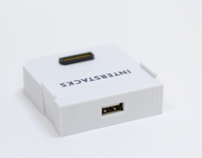
Menu
  • Use Cases
  • Stacks
  • Stackbuilder
  • MyStacks
  • Support
  • About Us
  • Contact
  • Use Cases
  • Stacks
  • Stackbuilder
  • MyStacks
  • Support
  • About Us
  • Contact
  • View Cart

Infrared remote hardware block

The Interstacks Infrared Remote hardware block can receive and transmit infrared remote control codes. There are no infrared remote control standards. This means that the number of key codes numbers in the many thousands. Each device to be controlled from an infrared remote control uses its own unique codes. The “Key Code” output terminal sends a five byte binary array when its receiver detects an infrared command. A typical message might be: Binary(‘\x0c\xe0\xe0\xfe\xf5’). These are five (hexadecimal) binary bytes. By sending a similar five byte binary array to the “Character In” terminal, the Infrared Remote block will transmit the key code.

The Infrared Remote block has a built-in infrared receiver and transmitter behind the block’s front label, in addition to connectors on its back for two external infrared transmitters and one external infrared receiver.

A typical Python script inside a software block to examine the five byte binary key codes might be:

x = message  # message from infrared remote Key Code output terminal
if (x[0]==‘\x0c’) and (x[1]==‘\xe0) and (x[2]==‘\xe0’): # match first 3 bytes of key code
  if (x[3]==‘\x88’):
     I.sendmessage(2, ‘0’)
  if (x[3]==‘\x60’):
     I.sendmessage(2, ‘1’)

Connectors on back

Looking into back:

Note that the Infrared Remote block also has a built-in infrared receiver and transmitter behind the front label.

Block properties and terminals

Properties
Type (uuid): Module Type
Version (int): Firmware Version

Power (int): External transmit power. 0 low power 1 high power. Default low power. Do not use high power with small, external IR LEDs.

Terminals
“Properties” – in (List or Property Name string): To set property. Send property name, Value. For example [’N’,’netname’]. To get property, just send property name. For example. ’N’
“PResponse” – out (List or True) : On set, responds with True when done. On get, responds with list. For example [’N’, ‘netname’].

“Character Out” – out (String): One char string of interpreted IR code.
“Character In” – in (String or Binary Array): Transmit IR code for character. or Binary array. Transmit keycode. Will often be 5 byte key code.
“Key Code” – out (Binary array): Received keycode. This will often be 5 bytes but could be a several hundred byte raw run length encoded edge time sequence.

Refer to documentation on many other topics at interstacks.com/knowledge-base.
Please email info@interstacks.com with any questions.

Read More

Audio hardware block

The Interstacks Audio hardware block can play musical notes via its built-in MIDI music synthesizer, play sound files, and generate digitized audio data. The block has a small speaker and microphone inside its plastic case, as well as connectors on the back for plugging in an external speaker or external microphone.

Simply send a character string, like ‘cde’, to the “Music Note” input terminal to hear three music notes. Try “CDEFG” to hear notes an octave higher. You can also send raw MIDI commands. See the detailed specification sheet below for more information.

The “Sound Data In” terminal can play MP3, WAV, and AAC encoded sound files. This can get a bit complicated as you need to use the “Play FC” flow control output terminal to manage sending data into the Audio block. Example projects and software blocks will be available soon. By using the built-in or external microphone, you can record (digitize) sound. The sound data is sent out of the “Recorded Sound” output terminal in the WAV sound format. The “Record FC” flow control input terminal is used to manage the sending of the sound data out of the Audio block. You start and stop recording by sending any message to the “Start Recording” and “Stop Recording” terminals. Alternatively, you can set a fixed recording time by setting property “Rec_Duration” in the Stackbuilder property editor.

Set Properties of Audio Block
To set properties in Stackbuilder: Select the Audio block by clicking on it once. Click in the “Property Editor” in the bottom right, in the “Initial Value” column for the property you want to edit (if a character or string, use quotes).

Connectors on back
Looking into back:

Note that there is a small speaker and microphone built-in to the module.

Block properties and terminals

Properties
Type (uuid): Module Type
Version (int): Firmware Version

Volume (int): Volume 0-100.
Bass (int): Bass 0-15.
Treble (int): Treble 0-15.
Speaker (int): 0 use internal speaker (defualt), 1 use external speaker.
Rec_Rate (int): 0-3. Audio recording sample rate. 0-8khz 1-16khz 2-32khz 3-48khz. Default 0. 16 bit mono IMA ADPCM. At 8khz, 4k bytes/second.
Rec_Duration (int): Maximum audio recording length in seconds. Default is 0 which is infinity.

Duration (int): Note duration in milliseconds for “Music Note” terminal (play musical note).
Instrument (int): 0-128. Instrument (MIDI “program”) number for terminal 2. 128 is percussions. For example: 0 grand piano, 19 church organ 24 acoustic guitar 40 violin 42 cello 56 trumpet 57 trombone 66 tenor sax 71 clarinet 73 flute 105 banjo 109 bag pipe 124 telephone ring 126 applause. For instrument 128, each note is a different percussion instrument, per MIDI GM1+GM2 table.
Mode (int): Audio module status. Echoes “Status” terminal. 0=nothing, 1=record, 2=audio stream, 3=midi

Terminals
“Properties” – in (List or Property Name string): To set property. Send property name, Value. For example [’N’,’netname’]. To get property, just send property name. For example ’N’.
“PResponse” – out (List or True) : On set, responds with True when done. On get, responds with list. For example [’N’, ‘netname’].

“Sound Data In” – in (Binary): Audio data (or MIDI format 0) in to play. MP3, WAV, AAC.
“Play FC” – out (int): Flow control.

“Music Note” – in (int or binary or string or list of ints): Play musical note (MIDI convention, middle C is 60, full range 0-127) for Property D duration (in mS), using Property P instrument (MIDI convention 0-128 instrument table. Percussion is 128). If percussion instrument selected, then notes become different percussion effects per MIDI GM1+GM2. Can also optionally embed note durations in binary data stream. If int > 128, following note duration is (int – 128) * 100ms. MIDI notes to “Music Notes” with different durations. Binary(‘\x86\x3c\x83\x3e\x86\x40\x84\x3c\x86\x40\x86\x3c\x86\x40’)

String. ‘a’ through ‘g’ and ‘A’ through ‘G’ map to notes with ‘c’ being middle c. and ‘C’ being octave above middle C. ‘c#’ will play C sharp. can send string like ‘abcc#dd#efgg#’. ‘1’ plays middle C. ‘2’ plays C sharp.
List of ints. A python list of ints can also be used. [60, 61, 62, 63] Advanced: If the binary data has \xFF as first value, then the rest of that data is used as raw MIDI commands. Note on is \x90. Note off is \x80. Program (Instrument) change is \xc0. Typical format is: \xFF, NoteOn or NoteOff, Note value, Velocity value (e.g. \x5a). You must send a value for velocity for each note. Binary(‘\xff\x90\x3c\x5a\x90\x40\x5a\x90\x43\x5a’) C chord. 3 notes on. Most instrument selections will have notes decay to zero eventually. A few instruments (church organ (19), rock organ (18)) will keep On notes playing forever until a NoteOff is sent. Binary(‘\xff\x90\x3c\x5a’) One note on. Binary(‘\xff\x80\x3c\x5a\x90\x40\x5a’) Same note off then new note.

“Music FC” – out (int): Flow control.

“Recorded Sound” – out (Binary): Audio data out that was recorded (digitized). WAV file.
“Record FC” – in (int): Flow control.
“Start Recording” – in (Any): Starts recording. For record length time (property “Rec_Duration”) in seconds. If streaming on, 0 stops recording. Sends audio data out “Recorded Sound” terminal.
“Stop Recording” – in (Any): Stop recording.
“Status” – out (int): Sound playing status. 0=nothing, 1=record, 2=audio stream, 3=midi

For Advanced users: A note about using flow control terminals for transferring large amounts of sound data in to, or out of, the Audio block. A negative number is the message size. A positive number is the number of messages that can be received. On getting the stack startup message (BP has been constructed message), flow control terminals send their initial information. For Audio, both input terminal “Sound Data In” and input terminal “Music Note” are flow controlled. “Play FC” terminal sends -1400 (1400 byte message size) and 6 for can receive 6 messages. “Music FC” terminal sends -10 for 10 byte message size and 20 for 20 messages. As data is sent in to the corresponding “Sound Data In” or “Music Note” in terminals, the flow control terminals will output the number of messages they are now ready to receive, having processed some number of previous messages. You are not required to use these terminals. They are only needed if you are trying to send large streams of data into the audio module. The “Record FC” flow control input terminal is used to manage the sending of sound data out of the Audio block’s “Recorded Sound” output terminal.

Refer to documentation on many other topics at interstacks.com/knowledge-base.
Please email info@interstacks.com with any questions.

Read More

Motors hardware block

The Interstacks Motors hardware block enables you to connect four DC motors or two stepper motors (4V – 10.8V DC max, 1 amp maximum). You can use motors in all kinds of mechatronic projects like robotics, small manufacturing motion platforms, and anything else that requires an actuator in the physical world. All motor power must be provided externally via a separate power supply. Typically 5 – 10.8V DC maximum. (see Adafruit, Sparkfun, Digikey). DC (4v – 7v) motors and four wire DC (4v – 11v) stepper motors can be purchased from many sources e.g. Pololu.

You use the ‘Mode’ property in Stackbuilder to define which types of motors will be connected. By sending the character ‘1’ to the appropriate Go/Stop input terminal, the motor will turn on. By sending the character ‘0’ to the Go/Stop input terminal, the motor will stop. Refer to the detailed property spec sheet for advanced options.

Set Properties of Motor Block
To set properties in Stackbuilder: Select the Motors block by clicking on it once. Click in the “Property Editor” in the bottom right, in the “Initial Value” column for the property you want to edit (if a character or string, use quotes).
The “Mode” property specifies the types of motors you want to connect (see below). 0 for four DC motors or 1 for two DC stepper motors. Refer to the detailed property spec sheet for advanced options.

Motors Connector – Looking into back

If ‘Mode’ property is set to 0, specifying four DC motor functionality.

If ‘Mode’ property is set to 1, specifying two stepper motor functionality. (4v – 11v DC stepper motors. Four wire).

( Four wire stepper motors often have the following color coded wiring that would correspond to the Motors block connector.
Please check the spec sheet for your motor.)

All motor power must be provided externally via a separate power supply. Typically 4.0 – 10.8V DC maximum. (see Adafruit, Sparkfun, Digikey)

Block properties and terminals

Properties
Type (uuid): Module Type
Version (int): Firmware Version

Mode (int) (0-3): Motor module configuration. Supports Four low current DC motors or 2 stepper motors. 0: Four DC motors (motors 1-4) 1: Two Stepper motors (motors 1-2) 2: One Stepper (motor 1) Two DC ( motor 2 motor 3) 3: Two DC motors (motor 1-2) / One Stepper (motor 3)

M1_Speed (int): Motor 1 speed. 0-1000. for dc motors, its PWM duty cycle %. (for steppers, its PPS (pulses/steps per second). with 1.8 degree stepper, 300 RPM at 1000)
M2_Speed (int): Motor 2 speed. 0-1000
M3_Speed (int): Motor 3 speed. 0-1000
M4_Speed (int): Motor 4 speed. 0-1000

SM1_Accel (int): Stepper 1 start acceleration. in pulses per second per second. linear slope
SM2_Accel (int): Stepper 2 start acceleration. in pulses per second per second. linear slope
Holding_Current (int): Holding current for steppers. Defines holding torque. 0-100 max. default 50. Motor can get hot if hold too much.
SM1_step_size (int): 1/4 stepping on/off stepper 1. default off 0. on 1. if on, 1/4 stepping enabled, 800 step per revolution vs 200 typically.
SM2_step_size (int): 1/4 stepping on/off stepper 2. default off 0. on 1. if on, 1/4 stepping enabled, 800 step per revolution vs 200 typically.
SM1_Scale (int): For stepper 1, number of steps for full rotation. default 200. (1.8 degree steppers) This is specified by the stepper motor manufacturer.
SM2_scale (int): For stepper 2, number of steps for full rotation. default 200. (1.8 degree steppers) This is specified by the stepper motor manufacturer.

Terminals
“Properties” – in (List or Property Name string): To set property. Send property name, Value. For example [’N’,’netname’]. To get property, just send property name. For example. ’N’
“PResponse” – out (List or True) : On set, responds with True when done. On get, responds with list. For example [’N’, ‘netname’].

“Go/Stop 1” – in (string): Motor 1 go/stop. ‘1’ go, ‘0’ stop. If go, will run continuously.
“Stopped 1” – out (int): Motor 1. Sends int of 0 when stepper motor stopped.
“Direction 1” – in (String): Motor 1 Direction ‘0’ forward. ‘1’ reverse.
“Speed 1” – in (int): Motor 1 Speed. 0-1000. (this also sets the speed property).

“Go/Stop 2” – in (string): Motor 2 go/stop. ‘1’ go, ‘0’ stop. If go, will run continuously.
“Stopped 2” – out (int): Motor 2. Sends int of 0 when stepper motor stopped.
“Direction 2” – in (String): Motor 2 Direction ‘0’ forward. ‘1’ reverse.
“Speed 2” – in (int): Motor 2 Speed. 0-1000. (this also sets the speed property).

“Go/Stop 3” – in (string): Motor 3 go/stop. ‘1’ go, ‘0’ stop. If go, will run continuously.
“Stopped 3” – out (int): Motor 3. Sends int of 0 when stepper motor stopped.
“Direction 3” – in (String): Motor 3 Direction ‘0’ forward. ‘1’ reverse.
“Speed 3” – in (int): Motor 3 Speed. 0-1000. (this also sets the speed property).

“Go/Stop 4” – in (string): Motor 4 go/stop. ‘1’ go, ‘0’ stop. If go, will run continuously.
“Direction 4” – in (String): Motor 4 Direction ‘0’ forward. ‘1’ reverse.
“Speed 4” – in (int): Motor 4 Speed. 0-1000. (this also sets the speed property).

“Num Steps 1” – in (int): Stepper 1 Number of steps to move. does go – move n steps – stop.
“Num Steps 2” – in (int): Stepper 2 Number of steps to move. does go – move n steps – stop.
“Degrees 1” – in (int): Stepper 1 move N degrees.
“Degrees 2” – in (int): Stepper 2 move N degrees.

“Motor Fault” – out (int): Sends a 1 if motor controller overheats.

Refer to documentation on many other topics at interstacks.com/knowledge-base.
Please email info@interstacks.com with any questions.

Read More

Servos hardware block

The Servos hardware block allows you to connect up to six DC (4.8v – 6v) servo motors . All motor power must be provided externally via a separate power supply. Typically 5v – 7v DC. (see Adafruit, Sparkfun, Digikey). DC (4.8v – 6v) servo motors can be purchased from many sources. See Adafruit, Sparkfun, Servocity and many others. Manufacturers include Futaba, Towerpro, and others. Servos can typically be positioned over 180 degrees only (half rotation). It is possible to also buy continuous rotation servo motors.

In your stack blueprint, to set the servo position, send the input terminal an integer between 0 and 1,000.


Servos Connector – Looking into back of block


All motor power must be provided externally via a separate power supply. Typically 4.8 – 6V DC. (see Adafruit, Sparkfun, Digikey)

Servo connector plugs in vertically. For many DC servos, the orange or white wire would go to the top pin e.g. S1

For advanced users, the full blocks detail spec sheet with all properties and terminals.

Block properties and terminals

Properties
Type (uuid): Module Type
Version (int): Firmware Version

Terminals
“Properties” – 0 in (List or Property Name string): To set property. Send property name, Value. For example [’N’,’netname’].
To get property, just send property name. For example. ’N’
“PResponse” – 0 out (List or True) : On set, responds with True when done.
On get, responds with list. For example [’N’, ‘netname’].

“Servo 1” – in (int): 0 – 1000 controls servo position.
“Servo 2” – in (int): 0 – 1000 controls servo position.
“Servo 3” – in (int): 0 – 1000 controls servo position.
“Servo 4” – in (int): 0 – 1000 controls servo position.
“Servo 5” – in (int): 0 – 1000 controls servo position.
“Servo 6” – in (int): 0 – 1000 controls servo position.

Refer to documentation on many other topics at interstacks.com/knowledge-base.
Please email info@interstacks.com with any questions.

Read More

Serial hardware block

Connect external sensors, small character displays, RGB LED chains, GPS receivers and many other peripherals. This block supports UART (3.3V), I2C, and SPI serial interface protocols. There is a ten wire screw terminal connector on back for connecting wires to the block.

There are many vendors to purchase sensors, sensor breakout boards, RGB LED chains, and small LCD character displays that can be connected to Interstacks. Some include Adafruit, Sparkfun, and Digikey.

There are a very large number of external devices that can be connected to the Interstacks Serial block using one of the three standard serial protocols. The serial block can communicate using all three types of serial connections simultaneously. Each type of serial communication has specific properties that are set in the Stackbuilder Property Editor that define their behavior.

To set properties in Stackbuilder: Select the Serial block by clicking on it once. Click in the “Property Editor” in the bottom right, in the “Initial Value” column for the property you want to edit (if a character or string, use quotes).

Serial Connector – Looking into back

DC Out is 3.3V if property Voltage is 1 (default). 5V if property Voltage is 0. Can supply 400 mA.

RGB LED chains
The Interstacks Serial block directly supports two types of RGB LED chains via the SPI serial interface. See the Neopixel line from Adafruit (part # 1426 and many others). By setting the L_Device property you can choose the type of RGB chain: 0 none, 1 LPD8806 type, 2 WS2812 (neopixel) type. After doing this, you can simply send character strings to the SPI Send input terminal to set the colors of the RGB LEDs in the chain. For example, ‘rrrrrrrr’, to set 8 LEDs to all red. (more info below).

I2C Sensors
Many sensors use the I2C serial protocol. For example: Light level sensors using the BH1750 or TSL2591. Temperature sensor from Sparkfun TI TMP102 breakout (part # SEN-11931). From Sparkfun, invensense breakout. 3 axis gyro. Invensense ITG3200.

LCD Character Displays
There are many small, LCD character displays that can be purchased and connected to the Serial module UART. For example: a 2 line x 16 character display from Digikey: Newhaven Display NHD-0216K3Z-NSW-BBW-v3.

Block properties and terminals

Properties
Type (uuid): Module Type
Version (int): Firmware Version

U_Baud (int): Uart baud rate. default 9600 baud.
U_Enable (int): Uart on 1 off 0. default is on.
U_Receive (int): Uart. Terminal 1 output chars received or not. int. 1 on (default) 0 off.
U_Prepend (Binary): Uart Bytes to prepend to all Uart strings sent to Terminal 1.
(This is useful for Uart devices like small LCD displays so can prepend a clear screen).
U_IntToStr (int): Uart Convert ints to string before sending out Uart. int 1 on 0 off. (This property is the letter “i” upper or lowercase)

I2C_Speed (int): I2C speed. 0 default is 100khz. 1 is 400 khz.
I2C_Addr (int): I2C slave address. default is 80 ($50)
(Note: this should be the 7 bit I2C slave address. Some data sheets call out the 8 bit version, some the 7 bit.)
I2C_Bytes (int): I2C number of bytes to read. can be 1-4. default is 1.
I2C_Rate (int): I2C Sample rate for send value if changed. Only valid for I2C auto detect terminal.
Value is samples per second. Default is 0 or no send.

I2C_Device (int): I2C if we auto-detect an I2C device, put its I2C device ID here. A scan for I2C devices is done on power up and when this property is read.
Device IDs:
TI_TMP102_TEMP \x49 // sparkfun breakout. TI TMP102. default is $49.
VISHAY_VCNL4000_PROXIMITY \x13 // adafruit breakout. does short range, under 7″ proximity.
INVENSENSE_ITG3200_GYRO \x69 // sparkfun invensense breakout. 3 axis gyro.
BH170 light level sensor \x23
TSL2591 light level sensor \x29

SPI_Clock (int): SPI clock frequency for SPI serial interface. default is 100khz.
SPI_Protocol (int): SPI protocol. 0,1,2, or 3. default is 0. Idle clock polarity and use first or second clk pulse.
00 – clock low, first edge. 1 – clock low, second edge. 2 – clock high, first edge 3-clock high, second edge
SPI_CS (int): SPI CS output pin. 0 low, 1 high. The default is 0.
L_Device (int): Type of RGB LED chain connected to SPI port. 0 none, 1 LPD8806 type, 2 WS2812 (neopixel) type.
This module directly supports connecting two types of RGB LED strips to the SPI port.
If this property is set to non-zero, data received by the SPI Send terminal is interpreted as meant for one of the RGB LED strips.

Voltage (int): 0 to set external power terminal to 5V. 1 for 3.3V (default).
L_Brightness (int): Brightness 0-9 for RGB LED strip when used with string input. If binary input, has no effect.

Terminals
“Properties” – in (List or Property Name string): To set property. Send property name, Value. For example [’N’,’netname’].
To get property, just send property name. For example. ’N’
“PResponse” – out (List or True) : On set, responds with True when done.
On get, responds with list. For example [’N’, ‘netname’].

“UART Send” – in (String, Binary, int): send string to UART, we only send valid ascii portion. Also accept binary raw bytes. Also int < 256. send out as raw byte.
“UART Receive” – out (String): Single byte received by UART. Sent as string.
“UART Receive Str” – out (String): Ascii strings that are identified by a CR or LF or CRLF termination.

“I2C Send” – in (String, Binary, int): I2C send data. (uses slave addess in property A) Also int < 256. send out as raw byte.
“I2C Request” – in (any): Request to read I2C data from slave.
“I2C Receive” – out (int): I2C read data. (uses slave address in property A, Number of bytes in property N)

“SPI Send” – in (String, Binary, int, list): accepts strings or binary (Binary) or int < 256. sends N bytes to SPI port.

You can optionally send a list [1, Binary data] that will toggle the SPI CS line before the send and after the send. Sometimes used with devices that separate command and data SPI sends via the CS line.

If property ‘L_Device’ is non-zero, this terminal will interpret a received message as meant for a RGB LED chain.
If a string, each character is interpreted as a color: r-red o-orange y-yellow g-green b-blue m-magenta p-purple
c-cyan z-brown w-white x-clear (off). There should be a color for each LED position in the chain.
In addition, an embedded ‘*’ followed by 0-9 will set the brightness for all subsequent colors.
Characters can be upper or lower case.
If binary, each LED is defined by 3 bytes in GRB format i.e. green first then red then blue.
The first 3 bytes are for the first LED in the daisy chain.
You must send all the values for the entire chain in one message.
Example: ‘yrrrbboogg’. for a 10 LED chain with colors yellow-red-red etc.
Example: Binary(‘\xff\x00\x00\x00\xff\x00\x00\x00\xff’) 3 LEDs, full bright green-red-blue.

“SPI Receive” – out (not implemented): gets data from SPI port and sends out terminal.

“I2C Auto Request” – in (Any): Trigger a I2C auto-detect sensor read.
“I2C Auto Receive” – out (int or char-int): I2C auto-detect sensors.
Also sends on value change based on P property, poll rate.
For sensors the firmware has “drivers” for, auto-detect what is connected, then a read sends out the value.
Temp-int, Light level-int, Proximity-int, gyro three char-int (x, y, z).

Refer to documentation on many other topics at interstacks.com/knowledge-base.
Please email info@interstacks.com with any questions.

Read More

I/O Expander hardware block

Connect buttons, switches, LED lights, and some (analog) sensors using the I/O Expander hardware block. This block supports eight analog inputs (0-3V) and/or 8 digital input/outputs. The digital inputs must be dry contact switch closures or 5V DC maximum. Digital outputs are 3.3V. Other hardware blocks such as the Analog In Universal block support other voltage ranges. There is a ten screw terminal connector on back for connecting wires to the block. The connector block can also output 3.3V or 5V for powering an external device.

There are many vendors to purchase sensors, sensor breakout boards, LEDs, and switches that can be connected to Interstacks. Some include Adafruit, Sparkfun, and Digikey.

If you are programming a stack yourself using the Stackbuilder authoring software, you can individually change the function of each of the eight I/O connections on the back of the I/O Expander hardware block by editing the corresponding property in the “Property Editor” in the bottom right. If your stack is pre-progrmmed via a Starter Kit or other Interstacks engineering support services, it will have been set up for the correct type of input.

To set properties in Stackbuilder: Select the I/O Expander block by clicking on it once. Click in the “Property Editor” in the bottom right, in the “Initial Value” column for the property you want to edit (if a character or string, use quotes).

Property HT1_Mode specifies the function of I/O connection 1 (the leftmost connection, looking into the back of the block). If you are connecting a switch (button), you would likely enter a 3 (digital input – send on change. Sends character ‘0’ or ‘1′). If you would like to drive a digital output e.g. an LED, enter a 1 (digital output – character ‘0’ low, ‘1’ high). If you would like to connect an analog input voltage that varies between 0 and 3V, set the property to a 4. Refer to the detailed property spec sheet for advanced options.

I/O Expander Connector – Looking into back

DC Out is 3.3V if property Voltage is 1 (default). 5V if property Voltage is 0. Can supply 400 mA.

Analog input signals
For analog input signals (0 – 3V), there are a number of signal processing features that can be enabled by setting the property for the I/O pin. The property set to 4 will simply read the voltage and output a number 0 -1000 whenever requested by sending any message to the input terminal that corresponds to that pin. If set to 5, the value will be automatically sent if its value changes by greater than the corresponding hysteresis property e.g. ‘HT1_Hysteresis’. If set to 6, a ‘1’ will be output if the value is greater than the comparison property e.g. ‘HT1_Threshold’. If set to 7, the value will be output every xx milliseconds based on the rate property for the pin e.g. ‘HT1_Rate’.

Block properties and terminals

Properties
Type (uuid): Module Type
Version (int): Firmware Version

HT1_Mode through HT8_Mode (int): Define behavior of I/O1 – I/O 8
0 nothing – never does anything.
1 Digital Output. Input terminal character ‘0’ or ‘1’ will make I/O pin low or high.
2 Digital Input. Output terminal will output character ‘0’ or ‘1’ dependent on state of I/O pin when requested by sending any message to the corresponding input terminal.
3 Digital Input Send Change. Will output on any state change.
4 Analog input on demand.
Output terminal will output an int (0 – 1000) based on analog voltage of I/O pin when requested by sending any message to the corresponding input terminal.
5 Analog input send change. Will output analog value on any change while filtering based on the value of the HTx_Hysteresis property for that pin.
6 Analog input with compare. Outputs a ‘1’ on change to above comparison value property. Outputs a ‘0’ on change to below comparison value property HTx_Threshold for that pin.
7 Analog input, send every x milliseconds based on update rate property HTx_Rate for that pin.
8 Digital input, accumulate duty cycle – Send update every HTx_Rate mS.
Accumulates the amount of high signal during update and sends this as value (currently samples once per mS).
(Have used with dust sensors (particulates)).
9 Digital edge count – send number of edges counted every HTx_Rate mS. (min 1ms pulses).

HT1_Hysteresis through HT8_Hysteresis (int): Hysterisis value for analog input send on change. default is 5. (multiples of about 3mV).
Each input used as analog input has its own hysterisis property, hence H1 through H8.
If analog input signal is noisy, use a higher value to reduce automatic value update sends.

HT1_Threshold through HT8_Threshold (int): Comparison value for analog input compare mode. default is 500.
HT1_Rate through HT8_Rate (int): Update rate, in milliseconds (1000 is 1 second), for analog input update rate mode.

Voltage (int): 0 to set external power terminal to 5V. 1 for 3.3V (default).

Terminals
“Properties” – in (List or Property Name string): To set property. Send property name, Value. For example [’N’,’netname’].
To get property, just send property name. For example. ’N’
“Presponse” – out (List or True) : On set, responds with True when done.
On get, responds with list. For example [’N’, ‘netname’].

Terminals In and out 1 – 8. See above description of properties 1-8.
“In 1”
“Out 1”
…
“In 8”
“Out 8″
If property defines I/O pin as output, character ‘0’ makes pin low, ‘1’ high.
If property defines I/O pin as digital input, will output character ‘0’ or ‘1’ based on level on I/O pin.
If property defines I/O pin as analog input, will output int with I/O pin analog voltage. Outputs a number 0 – 1000.
If analog input with compare, outputs on change character ‘0’ if below compare value and ‘1’ if above.

In HTx_Mode equal to 4, any message to the corresponding input terminal will cause the value to be sampled and sent out the output terminal.

Note: Digital inputs configured with weak pullups. so can connect buttons without external resistor.

Refer to documentation on many other topics at interstacks.com/knowledge-base.
Please email info@interstacks.com with any questions.

Read More

Posts navigation

Newer posts

Popular Articles

  • MyStacks Cloud Dashboard
  • Internet communication with HTTP block
  • Download and install Stackbuilder

Contact Us

Contact us with any questions or help with deploying your IoT projects.

CONTACT US

Connect

  • Facebook
  • Twitter
  • LinkedIn
  • Email

Sign up for the latest Interstacks news.

Join Our Newsletter
  Thank you for Signing Up
  Please correct the marked field(s) below.
1,false,1,First Name,2
Email:
1,true,6,Subscriber Email,2
Name:
1,false,1,Last Name,2

Copyright © 2023 Interstacks. All rights reserved. Privacy Policy | Terms and Conditions

Site by Imagebox